

Edge of Dock Leveler Installation |
 |
Manual & Installation DO NOT INSTALL, OPERATE OR SERVICE |
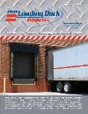
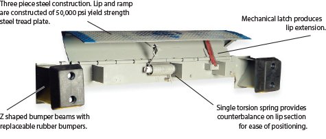
EZ-PULL EDGE OF DOCK LEVELER
| ||||||||||||||||||||||||||||||||||||||||||||||||||||||||||||||||||||||||||||||||||||||||||||||||||||||||||||||||||||


| SYMPTOM | POSSIBLE PROBLEM |
| When I raise the dock leveler the front lip does not extend outward. |
|
| When I raise the dock leveler the handle hits the dock surface. |
|
| The leveler will not raise enough to allow latch to catch. |
|
| The leveler is difficult to raise and lower into position. |
|
*Important: Specify model number and serial number when ordering parts.

LEVELER ASSEMBLY AND PARTS
|
PART |
DESCRIPTION |
|
EP72LIP |
FRONT LIP ASSY (STD) -- 15" LIP LENGTH |
|
EP72LIPR |
FRONT LIP ASSY (REEFER) -- 17" LIP LENGTH |
|
EP72DECK |
CENTER SECTION ASSY |
|
EPBUMPBASE |
BUMPER SUPPORT |
|
EPSA |
SPRING ASSY (INCLUDES LINKAGE ROD) |
|
ERB10 |
MOLDED BUMPER -- 13" X 10" X 4" W/ FASTENERS |
|
EPLINKROD |
LINKAGE ROD WITH PINS |
|
EPHANDLE |
HANDLE W/ BOLT |
|
EPLAT |
LATCH W/ BOLT |
|
EPCB10 |
BUMPER WITH STEEL BASE |
Complete Hydraulic Set-up Installation Instructions
For Factory Issued Hydraulic Unit

NOTE: FOR LO-DOCK APPLICATIONS CALL LOADING DOCK SUPPLY @ 1800-741-1258
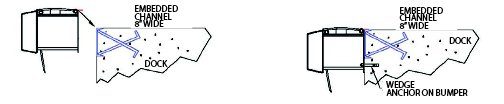
1.) Prior to mounting, refer to EZ-Pull dock parameters and mounting instructions for mechanical edge-of-dock levelers or lo-dock leveler for mounting the leveler unit.
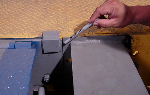
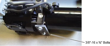
2.) Lift the lip of the EZ-Pull leveler to expose brackets as shown below.
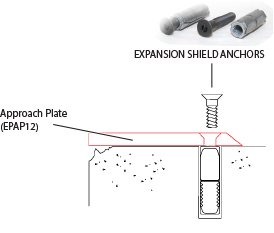
3.) Anchor mount plate as shown below.
4.) Weld EPHLBKT lower bracket in-line with the EPHUBKT upper bracket
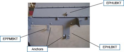
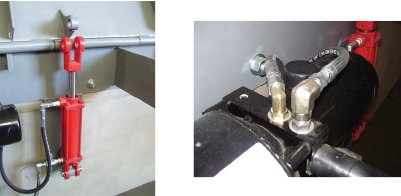
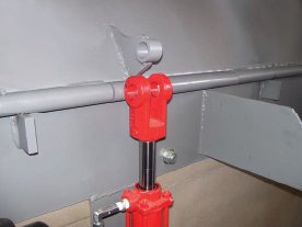
5.) Mount the MPOWERUNIT on the pump mount bracket EPPMBKT.
6.) Mount the MHYDCYLINDER onto the lower bracket EPHLBKT.
7.) Install and connect hoses as shown below.
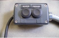
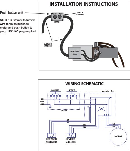
8.) Mount the switch (MPUSHBUTTON) on the interior of the building wall.
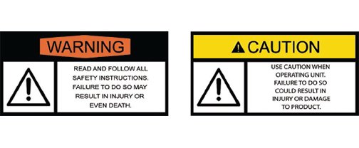
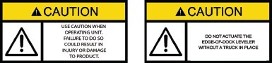
CAUTION
ONLY QUALIFIED PERSONNEL SHOULD ATTEMPT TO PERFORM THE FOLLOWING WIRING INSTRUCTIONS
IMPORTANT
9.) Item ships without hydraulic fluid. FILL RESERVOIR WITH COMMON GRADE HYDRAULIC FLUID. (Common Grade fluid is 150 46 viscosity-20W)
10.) Power the MPOWERUNIT and jog the motor to test wiring.
11.) Jog motor to extend the MYCDCYLINDER such to attach to the upper bracket EPHUBKT utilizing the provided pin and keepers
12.) Carefully lower the lip to its rest position.
13.) Press the forward and reverse button to complete a full cycle.
14.) Refer to the trouble-shooting guide if unit does not function properly.
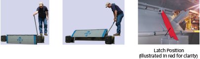
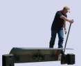
OPERATING INSTRUCTIONS
Hydraulic Dock Levelers
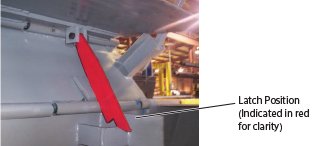
Step 1: With truck back into position and trailer door open, depress the reverse button until the latch falls into position. See Illustration Below.
Step 2: Once the latch falls into position, release the reverse button and depress the forward push button.
Step 3: The front lip will begin to extend forward, continue to hold the forward button until the front lip rests on the truck floor or the latch kicks off and the front lip lowers onto the truck floor.
Step 4: To return the hydraulic leveler to its resting position, for proper storage, depress the reverse button until the front lip clears the truck bed and raises into a vertical position.
Step 5: The hydraulic fluid will return to the tank. The deck section will slowly lower to its resting position parallel to the dock face.
Note: when leveler is not in use, keep lowered, stored position.
Complete Hydraulic Set-up Installation Instructions
For In-field Retro-fit of Existing Leveler Unit
NOTE: The leveler selected for the retro-fit hydraulic package must be in acceptable working condition.
1.) Lift the front lip of the Dock Leveler to expose the brackets as shown below.
2.) Remove the spring assembly leaving the deck stop and gusset.
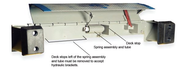
3.) Clean the surface and weld the brackets as shown below.
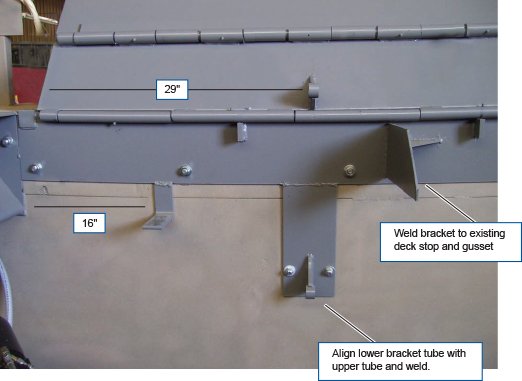
4.) Anchor the lower bracket to side of dock.
5.) Mount the MPOWERUNIT on the pump mount bracket EPPMBKT.
6.) Mount the MHYDCYLINDER onto the lower bracket EPHLBKT.
7.) Install and connect hoses as shown below.
8.) Mount the switch (MPUSHBUTTON) on the interior of the building wall.
CAUTION
ONLY QUALIFIED PERSONNEL SHOULD ATTEMPT TO PERFORM THE FOLLOWING WIRING INSTRUCTIONS
IMPORTANT
9.) Item ships without hydraulic fluid. FILL RESERVOIR WITH COMMON GRADE HYDRAULIC FLUID. (Common Grade fluid is 150 46 viscosity-20W)
10.) Power the MPOWERUNIT and jog the motor to test wiring.
11.) Jog motor to extend the MYCDCYLINDER such to attach to the upper bracket EPHUBKT utilizing the provided pin and keepers
12.) Carefully lower the lip to its rest position.
13.) Press the forward and reverse button to complete a full cycle.
14.) Refer to the trouble-shooting guide if unit does not function properly.

HYDRAULIC ASSEMBLY PARTS
|
Ref. |
QTY. |
PART |
Description |
|
A |
1 |
MHYDCYLINDER |
6" STROKE, TIE ROD HYD. CYLINDER |
|
B |
2 |
Y3414B |
FITTING REDUCER |
|
C |
1 |
MADAPTER90 |
90 DEG. ELBOW SHORT |
|
D |
1 |
MADAPTER90XL |
90 DEG. ELBOW LONG |
|
E |
1 |
YFCV |
FLOR CONTROL VALVE |
|
F |
1 |
MPOWERUNIT |
AC HYD-PWR UNIT |
|
G |
1 |
Y90ML |
90 DEG. ELBOW |
|
H |
1 |
Y30HH |
30" HYDRAULIC HOSES |
|
I |
2 |
** |
SOLENOID CONNECTORS |
|
J |
2 |
F3834H |
PUMP MOUNT BOLTS |
|
K |
1 |
EPHUBKT |
EP-HYD. UPPER BRACKET |
|
L |
1 |
EPPMBKT |
EP PUMP MOUNT BRACKET |
|
M |
1 |
MPUSHBUTTON |
WALL MOUNTED PUSH BUTTON |
|
N |
1 |
M442GANGBOX |
ELECT. JUNCTION BOX |
|
O |
1 |
M123RIGIDNIPPLE |
3" PIPE FITTING |
|
Q |
1 |
EPHDS |
EP-HYD. DECK STOP |
|
**INCLUDED MPOWER UNIT |
|||
Trouble Shooting Guide
(For all types of edge of dock units)
| SYMPTOM | POSSIBLE PROBLEM |
| Leveler will not pivot |
|
| Leveler will not extend forward |
|
| Lip not returning to stored position |
|
| Leveler not moving (motor running) |
|
| leveler will not move (motor not running) |
|